
The following is included in this e-tech newsletter:
- Troubleshooting the “mixing experience” in a co-rotating, intermeshing twin screw extruder
- Why consider retrofitting a co-rotating twin screw extruder for many biax and thin film applications?
- Sequence different extruders to facilitate multi-stage and disparate unit operations in one system
- Processing PLA and PHA bioplastics via TSEs: Tests & studies
- Featured twin screw formulas: Peak shear rate and shear stress
- Film, sheet and foaming capabilities expanded in Leistritz NJ process development laboratory
- Technical tip: Removing “stuck” elements from shafts
- Leistritz Extrusion Technology: Overview brochure
- 2022 Calendar of events
Troubleshooting the “mixing experience” in a co-rotating, intermeshing twin screw extruder

Co-rotating twin screws for continuous mixing
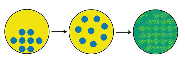
Twin screw extruders utilize unique screw-to-screw flows which are effective, rapid, efficient and capable of achieving both dispersive and distributive mixing. Co-rotating, intermeshing twin screw extruders mix polymers with fillers, additives and modifiers to impart desired performance properties that give the final part utility. Dispersive mixing and distributive mixing are strategically performed in the TSE process section.
Example of multiple components metered into a TSE
Homogenous formulation exiting TSE after mixing
Plastics compounding plays a role in all facets of modern life. Twin screw extruders are available for research and development purposes to process as little as a 50-gram batch, and for full-scale production at rates of 50,000+ kgs/hr. The attributes inherent with a twin screw extruder makes it the preferred manufacturing methodology for the continuous mixing of commodity and high-tech precision products.
Twin screw extruders componentry and operation are well understood, and have proven for 100 or so years in a myriad of 24-hr industrial settings (pellets and parts). That being said, a twin screw extruder is unlike a washing machine in that a variety of techniques must be integrated and applied to successfully mix a multi-component formulation.
A basic understanding about the interrelationships of the output rate/screws rpm, screw design and elements and viscosity management allows the user to troubleshoot a TSE process to achieve a high-quality, homogenous melt without degradation. A quick summary on these parameters includes:
Conditions regulating mixing intensity
Parameter | Gentle | Strong |
| TSE screw rpm Sometimes helps Sometimes hurts | Low | High
|
Degree screws fill | High
| Low
|
Temperature | High | Low |
| Extensional mixing & planar shear RT in mixers and number of mixing events | Low | High |
| Sequential feed Employed to capture and/or avoid shear stress | Depends | Depends |
A detailed article (featured in Plastics Technology Magazine) which discusses the interaction of these parameters (and other factors) in an in-depth way to troubleshoot the mixing experience in a TSE is available for download.
Why consider retrofitting a co-rotating twin screw extruder for many biax and thin film applications?
The physical, mechanical and barrier properties inherent with biaxially oriented films is why these are so prevalent in the flexible packaging market. These film systems often operate at more than 6 tons of film per hour! At these outputs, co-rotating twin screw extruders often have a lower investment-cost-to-output ratio compared to that of a single screw (SSE) and are now initially specified on most new biax film systems.

ZSE 135 MAXX biax film system
There are a multitude of legacy thin film systems that utilize single screw extruders (SSEs) where TSE replacements might be justified and considered. Besides investment cost, there are other process and economic reasons to replace an existing single with a twin screw, such as:
- Energy and heat transfer efficiencies
The greatest consumption of energy in most extrusion processes is the energy required to melt, heat and cool the raw materials. Compared to a SSE, the screws interaction in twin-screw extruder imparts energy from the motor more efficiently. Even with an added gear pump, these factors make TSEs 20-35% more energy efficient as compared to SSEs. Internal cooling bores in the barrel sections, too, are a more efficient heat transfer/cooling mechanism as compared to air-cooled SSEs. Furthermore, for hygroscopic materials like PET, devolatilization can be incorporated into the twin, eliminating the need for pre-drying – along with the expensive desiccant dryer and the energy required to operate.
- Process advantages
There are many process advantages inherent with co-rotating intermeshing TSEs:
- Elimination of a separate compounding process results in one less heat/shear history and degradation of the molecular weight for improved physical properties
- Self-wiping screws result in less gel formation for higher quality film and decreased screen changes
- A consistent and repeatable mixing experience with a controlled residence time distribution (ref. mixing article above) maintains a tighter molecular weight distribution, and therefore fewer high and low molecular weight tails (so less unmelts and die build-up)
- Eliminates the possibility of coalescence of dissimilar materials in the SSE process that can adversely impact the performance of the film
- Pre-mixing of edge trim and virgin materials prior to being fed back into the TSE via feeders with gravimetric controls facilitates consistent feeding and higher attainable %s of reclaim into the process
- Maintenance
Single screw extruders typically use barrels and screws made from a single machined piece of steel while components from twins are built in modular segments. Damage to the single screw extruder screw or barrel mandates replacement of the complete item. For TSEs, only the area of the screw or barrel worn or damaged needs replacement. The transition from SSEs to TSEs affords the opportunity to convert from DC to AC motors.
- Floor space
The “footprint” of a twin screw extruder is less than half that of a single extruder.
Leistritz Extrusion Technology would be pleased to audit your existing film system to provide an engineering plan and cost estimate so that you can consider retrofitting a twin screw extruder into an existing process.
Comparing TSE Feeding/Melting Zones for PLA and PHA Bioplastics
There are many grades of PLA and PHA resins. PLA is typically supplied as a pellet and requires a high torque TSE for processing. PHA is often a powder with a low bulk density. Both materials benefit from additives/lubricants and require optimized feeding zones for successful processing. Modifying early sections of the segmented screws to enhance feeding and processing was explored in the following experiments:

Test #1
A melting experiment was performed processing PLA (NatureWorks™ grade 4032D) using three screw designs with modified melting sections. PLA pellets with varying lubricant levels were processed on a ZSE 27 MAXX twin screw extruder (28.3 mm dia. screws, 1.66 OD/ID) were tested at different screw rpms with a constant 45 kg/hr feed rate.

Modifying the melting zone from a “standard” design resulted in lower torque and melt temperatures. Formulations were also tested with and without lubricants. As expected, when the lubricant content was increased, the torque and melt temperature both decreased.

Test #2
A series of experiments was performed processing an experimental grade PHA resin with 10% impact modifier (+ additives) on a ZSE 27 MAXX model TSE. Initial testing was performed with a standard PE type screw/barrel design, and the attainable rate was limited to 12 kgs/hr at 300 screws rpms. At higher rates and screw rpms the feedstock material backed-up in the feed throat and premature melting occurred. A 2nd process design that delayed melting and added an early atmospheric vent resulted in an increased rate (62 kgs/hr) at 800 screws rpm, also making a quality product.
Most twin screw extruders are processing “traditional” polymers. PLA, PHA and other bioplastic resins often require a different hardware configuration for success. Optimizing feeding and melting regions of the process section are a good starting point. Next steps include mixing, devolatilization and pumping.
Sequence different extruders to facilitate multi-stage and disparate unit operations in one system
There is a trend to sequentially combine multiple extruders in one system to economically extrude unique products. The systems can utilize two (or more) single screws, co-rotating and counterrotating twin screw extruders to take advantage of the unique performance of each type.
Tandem extrusion systems allow effective L/D ratios of 100+ to string together a series of unit operations using different type extruders at different screw diameters and screw rpms. An example is a tandem extrusion system to reclaim PVB from safety glass/windshields (a PVB film is sandwiched between two pieces of glass to create safety glass) while performing both compounding and devolatilization tasks, depicted as follows:

PVB reclaim tandem extrusion system
After the PVB film has been removed, granulated and cleaned (from windows or windshields) the following components can be integrated into a reclaim extrusion system:
- Metering system of PVB reclaim flakes into a co-rotating TSE
- Co-rotating TSE to devolatilize water from the wash step and disperse residual glass
- Screen changer to filter contaminants
- Gear pump to meter melt stream to a 2nd co-rotating TSE
- Co-rotating TSE with side stuffer to introduce fillers/fibers into melt stream
- Underwater pelletizing system
The utilization of tandem extrusion systems will expand to increase the efficiencies and expand the product range possible via extrusion….the possibilities are endless!
Download "Quick overview of commercially available twin screw extruders (TSEs)" (PDF)
Featured twin screw formulas: Peak shear rate and shear stress

End view twin screws and overflight gap
Definition of the overflight gap:
It is the space between screw tip and the barrel wall. The material entering into this gap experiences an extensional mixing effect and undergoes planar shear while in it.
The shear rate in the overflight gap in combination with the screws rpms allows the peak shear rate to be calculated as follows:
Peak shear rate = (π*D*n)/(h *60) where D = screw dia., n = screw rpm, h = overflight gap.
So for a TSE with 77-½ mm OD screw and 0.55 mm overflight kneader gap @ 600 rpms: (3.14*77.5*600)/(0.5 * 60) = 4867 sec.-1

Rotating kneader/mixing elements with overflight effect
The peak shear rate calculation is an oversimplification of the mixing effect (because extensional flow mixing and other mixing effects are essentially being ignored). It is, however, a useful benchmarking tool to troubleshoot the “mixing experience” since it’s easy to calculate.
Peak shear rate can be used in concert with viscosity to calculate shear stress to accomplish dispersive mixing:
Shear stress = Peak shear rate x Viscosity
In the early stages of the extruder viscosities are higher and produce high stress rates that cause dispersive mixing, or can cause degradation of shear sensitive materials. In the latter stages of the TSE process the viscosities have fallen and decreased viscosities produce comparatively low stress rates.

TSE process section with pressure and viscosities denoted
Increased cooling can increase the viscosity of the melt to achieve dispersive mixing. It must be again noted that shear stress is not a measurement of extensional mixing, which is complicated to calculate and requires modeling, but does provide a benchmark and insight into the dispersive mixing effect.
Test, don’t guess!
Film, sheet and foaming capabilities expanded in Leistritz NJ process development process laboratory
Co-rotating twin screw extruders mix plastics with additives and fillers to impart desired properties. The end product is often a pellet that’s then processed on a molding machine or single screw extruder. Pellets are either strand cut or die face cut. 98% of the time the cooling medium is water, but not always.

ZSE 27 MAXX sheet system in Leistritz Extrusion process development lab
The Leistritz Extrusion New Jersey process development laboratory is unique in that both pellets and/or film sheet samples are possible. Direct extrusion of film/sheet/filaments via twin screw extrusion allows for rapid prototyping for as many as 10 samples/hr.
The Leistritz process development laboratory includes:
- 5 twin screw extruders: ZSE 12 MAXX to ZSE 50 MAXX
- Strand, underwater and hot face pelletizing (air quench and water quench)
- 40+ feeders: pellets, powders, fibers, liquids, reclaim
- Downstream: film/sheet, tube/profile
- Film/sheet samples from 50 mm to 1 meter in width
- Up to 5-layer coex structures
- Lamination of substrates
- 3D filament extrusion
- Supercritical injection: foaming and stripping
- Devolatilization: 60/1 L/D, multi-stage, atmospheric and vacuum venting
- Tandem TSE system setups
Don’t hesitate to contact us to discuss your process development needs!
Download "Overview of Film, Sheet, and Lamination Equipment for Life Science Installations" (PDF)
Technical tip: Removing screw elements from shafts
A technique for removing elements is to heat each element with a propane torch and hammer on it with a pneumatic impact hammer tool with brass-tipped punches (auto mechanics use this device to remove muffler pipes).

Twin screws after removal
The basic method for removing screw elements is as follows:

Screws on assembly table
- Work on the screws immediately after cleaning off the outer surfaces, while they’re still hot. If they’ve cooled down, put one or both screws back in the hot extruder barrel for 20 minutes or so to heat it back up. Separate the 2 screws. Work on one at a time.
- Support large screws evenly using blocks since long shafts can deflect and cause assembly issues.
- Unscrew the tip with gloves. Try to remove the last element. If it slides off the shaft, great. If not, take the propane torch and heat the element. This may take some time…. try to heat the elements evenly…. and be patient.
- Now remove the element by pulling it straight toward the shaft end. If it doesn’t budge, you will need a brass drift punch and a hammer.
- Start by angling the brass punch against the screw flight, toward the direction you want it to move, and give it a few hits. Keep heating and hammering until the element moves. Once it’s off, try the next one.
- As each element is removed from the shaft, brush-clean and scrape the exposed shaft, to make it easier to remove subsequent elements.

A particularly useful screw element removal device is a pneumatic impact gun (or air hammer): an off-the-shelf, inexpensive tool that can by modified with a brass tip (or chisel) to “hammer” the elements off the shafts.

Impact gun and brass tip to help screw removal
It’s a little noisy, but and works great at loosening “stuck” screw elements without damaging the elements or shafts.
Download: "Get Better at Swapping Out Your Twin-Screw Elements"

Leistritz Extrusion Technology:
Overview Brochure
A 16-page brochure describes the range of twin screw technologies and services available from Leistritz.
Leistritz Extrusion 2022 Calendar of Events
Join us at one of the following events - we are looking forward to meeting you!
| AMI Thermoplastic Concentrates | Jan 25 – 27 | St. Augustine, FL |
| AMI PE Films | Feb 1 – 3 | St. Augustine, FL |
| SPE Polyolefins Conference | Feb 13 – 16 | Galveston,TX |
| Plastimagen | Mar 8 – 11 | Mexico City/ Mexico |
| PTXPO | Mar 29 – 31 | Rosemont, IL |
| Plastech West/MDM | Apr 12 – 14 | Anaheim, CA |
| SPE ANTEC | June 14 – 15 | Charlotte, NC |
| SPE Precision Topcon | June 21 – 23 | Nashville, TN |
| SPE CAD RETEC | Sep 12 – 14 | Orlando, FL |
| AAPS 2022 | Oct 17 – 19 | Boston, MA |
| K Show | Oct 19 – 26 | Duesseldorf/ Germany |
| Leistritz Twin Screw Extrusion Workshop | Nov 29 – Dec 1 | Branchburg, NJ
|
We look forward to serving you in the future.
For additional information on anything contained in this newsletter please contact us
Team @ Leistritz Extrusion
Leistritz Extrusion Technology
175 Meister Ave. Somerville, NJ, 08876, USA
Tel: 908/685-2333
Email: sales@leistritz-extrusion.com
Website: extruders.leistritz.com