
The following is included in this e-tech newsletter:
- Understanding boundary conditions in a TSE: What limits operating at higher rates?
- Free on-demand webinar: Compounding of bioplastics and natural fiber composites on TSEs
- Featured twin screw formula: Residence time in a twin screw extruder
- Tandem extrusion capabilities expanded in Leistritz NJ process laboratory
- Technical tip: Install insulation blankets on barrels, adapters and dies
- Technical tip: Mezzanine and feeder re-loading guidelines
- Leistritz Extrusion Technology overview brochure
- Leistritz Extrusion 2023 calendar of events
- Download this newsletter as pdf
Understanding boundary conditions in a TSE: What limits operating at higher rates?
Co-rotating, intermeshing twin screw extruders mix plastics with additives and fillers to impart desired properties into the final product. Dispersive/distributive mixing and venting operations are strategically performed in the TSE process section. As with most manufacturing processes, it is often the goal of a twin screw extrusion system to operate at the maximum attainable rate while making a quality product.
By definition, a “boundary condition” is an operating parameter that prevents higher throughput rates from being achieved. A simple example is screw speed/rpms, whereas if screw rpms are increased from 400 to 800, attainable kgs/hour should also double, assuming another boundary condition is not encountered.
Examples of typical boundary conditions are as follows:
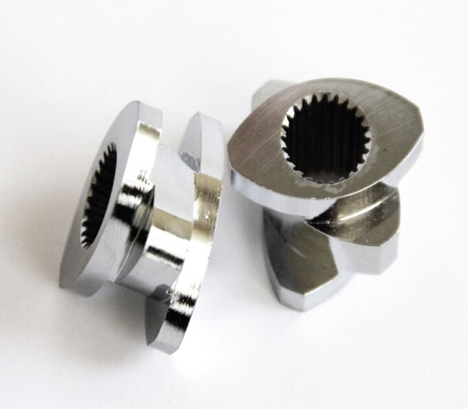
TSE element of asymmetrical splined shaft
Torque
A torque limited process is when there’s not enough power from the motor to turn the screws and pump the materials through the TSE process section and front end/die system. The screw shaft is what limits torque transmission in a TSE. The screw shaft rating is denoted in Newton-Meters (NM) or equivalent (both shafts) and design factors include cross-sectional area, shaft metallurgy, spline geometry and the shaft hardening process. State-of-the-art asymmetrically splined shafts transmit power from the motor and direct a tangential force vector into the screws.
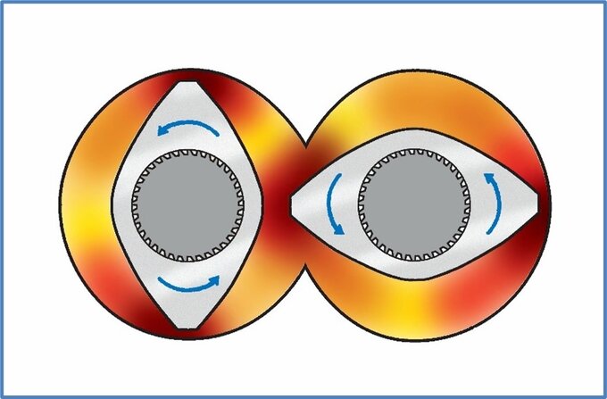
End view of ZSE MAXX with hi-torque asymmetrical splined shafts and TSE free volume depicted in orange
Processing of a fractional melt HDPE or PP formulation might be torque limited, so a TSE with a higher NM torque rating (all else being equal) will run at a higher rate than a TSE with a lower torque rating. TSE factors that would facilitate an increase in rate for a torque limited process might include removing several kneading elements and increasing zone temperature setpoints in the melting zone.
Volume
A volume-limited process occurs when the free volume in the TSE prevents more material from being metered into the process section. The Outside Screw Diameter divided by the Inside Screw Diameter, referred to as the OD/ID ratio, is an indicator of the available free volume in a TSE at a given screw diameter. Since twin screw manufactures do not have standardized screw diameters, the cc/diameter value is typically the best indicator. As an example, when comparing a 70 mm TSE with 1.55 OD/ID ratio and 240 cc/dia. volume to a ZSE 75 MAXX with 1.66 OD/ID ratio and 300 cc/dia. volume, a 30 % throughput rate increase can be expected, all else being equal.
Other methods of increasing the attainable rate of a volume limited process are targeted at maintaining feed densities and can include: optimizing material handling equipment, minimizing the drop distance of the LIW feeder to the TSE (or side stuffer), oversizing the side stuffer screws, vacuum assisted feeding, modifying barrel temperature profiles, and improving screw and vent design(s).
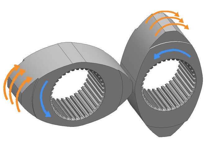
Mixing mechanism in wide kneading/mixing elements for dispersive mixing
Mass Transfer - Dispersive Mixing
Dispersive mixing requirements for color masterbatch for thin film or fiber applications may also set a boundary condition and be the limiting factor at achieving higher rates. Dispersive mixing relies on the strong forces being applied by rotating screws against the polymer matrix. Wider kneading elements accentuate extensional mixing and planar shear effects that result in dispersive mixing. Narrow kneading elements, by comparison, facilitate high division rate mixing with minimal extensional effects, causing a distributive mixing effect. Kneading elements can be arranged with a forward pitch (less aggressive), neutral or reverse pitch.
The following statements help to understand the mixing effects inherent with any TSE
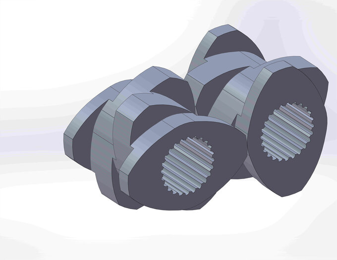
Example kneading element block: narrower disks = distributive mixing and wider disks = dispersive mixing
- Channel region: The mixing rate in the TSE channel region is similar to that of a single screw extruder (and is much lower as compared to the other TSE mass transfer regions)
- Overflight gap: The area between the screw tip and the barrel wall is where the material undergoes significant planar shear effects
- Extensional mixing: Extensional mixing occurs as the material “accelerates, stretches and breaks” in the transition from the channel region to the overflight gap
- Apex (upper/lower): Upper and lower apex regions are where the material “feels” the 2nd screw that results in directional flow changes, compression/expansion and axial mixing effects
- Intermesh: A small, finite amount of material passes between the screws and experiences intensive shear forces (and possibly degradation)
Feed rate versus screws rpm, with the screw design and temperature profile, regulates the mass transfer/mixing properties of the process.
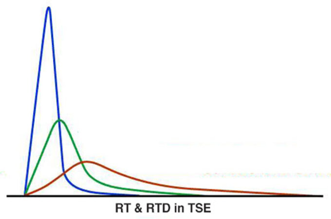
Highly dispersive mixing applications run at comparatively lower throughput rates. As the rates are decreased or increased (at a constant screw rpm) the materials spend more or less time in mixing zones where shear effects and extensional flow fields are dominant, and thus the “mixing experience” is impacted.
Mass Transfer - Devolatilization/ removal of gases
TSEs are ideally suited for devolatilization as the pressure gradient in the TSE process section is easily designed to accommodate zero pressure under vents to prevent vent flooding. Devolatilization is a mass-transfer limited process where unreacted monomer, solvent, water or other undesirable volatile contaminants are removed from a polymer melt (up to 25 % is viable). Increasing the screws rpm and/or decreasing the feed rate generally improves DV efficiencies. Vents can be sequenced and atmospheric, or vacuum venting can be applied to further enhance devolatilization effects. At high screw rpms, degradation of the formulation may occur (as other boundary conditions may be encountered).
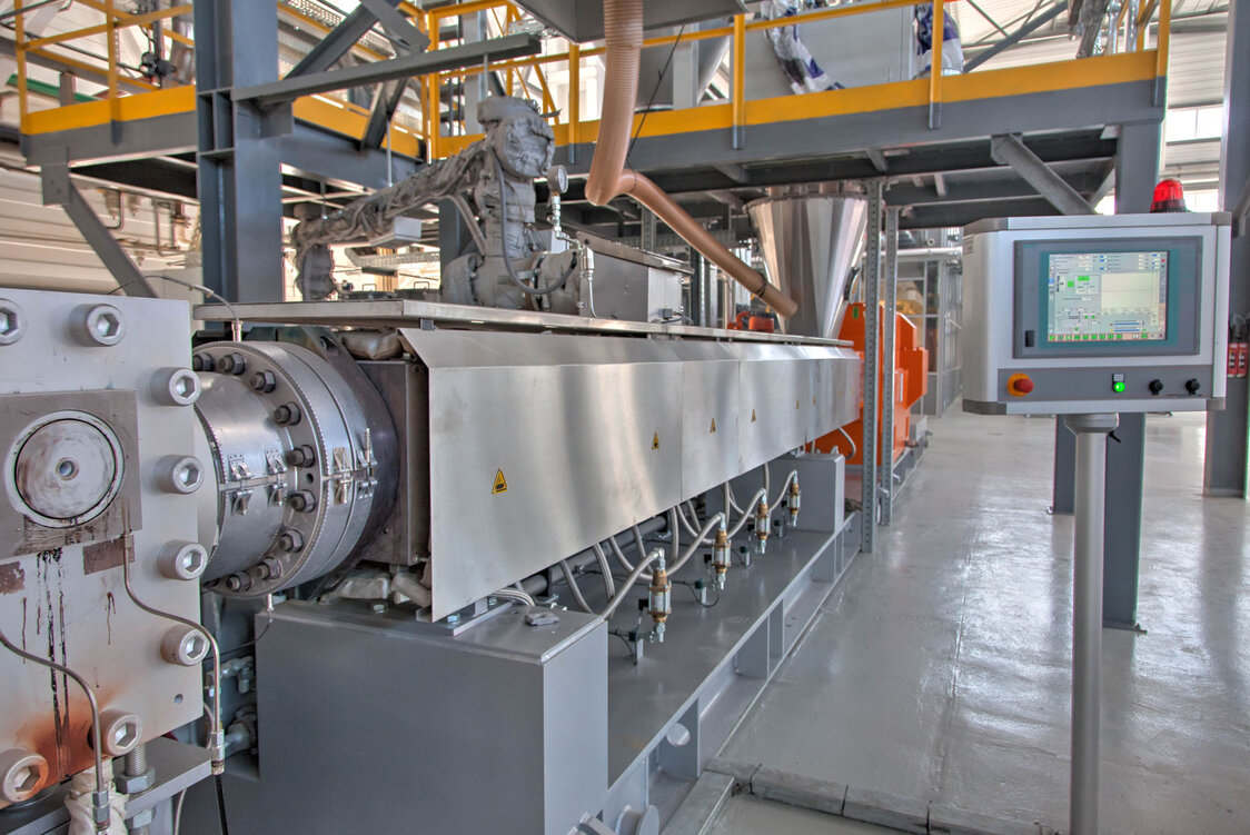
Heated/insulated vent stack attached to ZSE MAXX process section
Factors that affect devolatilization efficiencies include:
Residence time under the vent or vents - longer is better but…
- Oxygen, shear, time, and temperature may contribute to degradation and side reactions
- Understand kinetics of degradation
Surface area of the melt - higher is better
- Smaller melt pools
- Increase screw rpms
- Decrease rate
Surface renewal - higher is better
- Renewed surfaces come from rolling pools and partially filled screw channels
- Increase screw rpms
Melt temperature (Tm):
A balance must be made to impart enough shear (and energy) into the process to melt the polymer while also facilitating mixing/devolatilization with minimal degradation effects. Without exception, elevated Tm results in degradation of polymer formulations. A myriad of factors directly impact Tm, including but not limited to:
- Screw rpms (lower is often better, lower peak shear)
- Melting zone (extended melt zone and high temperature setpoints might help)
- Mixing elements (minimization is best if mixing quality is still achieved)
- Discharge pressure (lower is better due to less overflight mixing from pumping elements)
- OD/ID ratio (higher OD/ID ratio results in lower average shear)
- Barrels design (intensive cooling bores help, 2 inlets/outlets per barrel is deemed state-of-the-art)
The residence time in a twin screw process section is typically in the 15 seconds to 1+ minute range. Extended residence times at elevated temperatures may be the primary cause of degradation as compared to the TSE discharge Tm. Front-end systems that include screen changers, gear pumps and dies will dictate a lower Tm from the TSE and must be anticipated.
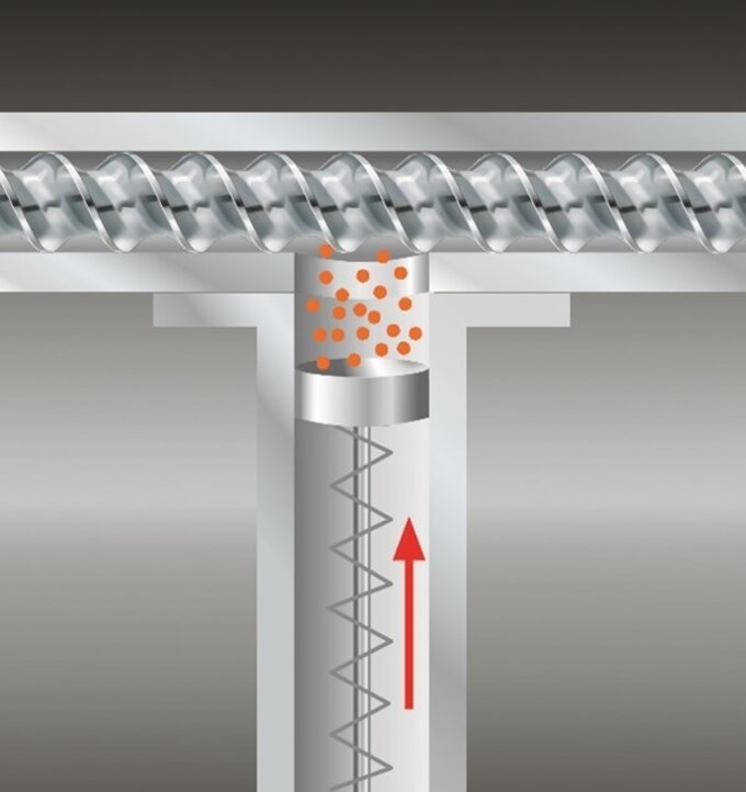
Example of a micro-plunger feeder (US patent 7,954,991 B2) for small batch process in a TSE
Scarcity/ cost of raw materials during the R&D phase
In early-stage development, lack of availability and relative high cost of raw materials is a common problem. So, the challenge is to extrude a usable sample that can be scaled-up. To accommodate limited batch processing, twin screw extruders may be specified with low volume screws (1.2/1 OD/ID ratio with 1 cc dia. Free volume) and specialty feed mechanisms employed for micro-batch sampling. (i.e. 50 grams) to allow sampling for scale-up purposes.
Upstream and/or downstream limited
A ZSE MAXX system is just like a chain, it is only as strong as the weakest link. There might be multiple (2 - 10) feed streams to the twin screw extruder. A die and downstream system are attached to the ZSE MAXX front-end. If any component in the manufacturing “train” cannot handle the required rate, the overall throughput of the system will be limited by that piece of equipment.
Download the white paper Understanding TSE Boundary Conditions (PDF)
Free on-demand webinar Compounding of Bioplastics and Natural Fiber Composites on TSEs
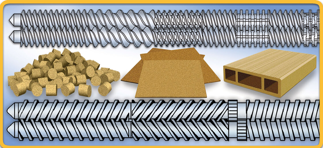
You are invited to access a free ½ hour on-demand webinar entitled:
Compounding of Bioplastics and Natural Fiber Composites on Twin Screw Extruders - Part 1
Twin screw extruders are the preferred device to mix polymers, natural fibers, and bioplastics. The final product can be pellets, film, sheet, pipe/profile, filaments and/or fibers. Relevant theory, tips and test results will be presented. The following topics will be addressed:
- Continuous mixing of heat- and shear-sensitive bioplastic formulations via twin screw extruders
- Matching twin screw barrel geometries to unit operations
- Comparison of co-rotating and counter-rotating twin screw extruder designs
- Devolatilization theory, techniques, and practices
- Upstream material handling and downstream system considerations
Featured twin screw formula: Residence time in a TSE process section
Residence time (RT) is a challenging parameter to calculate, particularly because the process in a TSE is a combination of partially and fully filled zones. In lieu of access to computer modeling, to estimate quickly and easily separate RT separate equations are used for flighted and non-flighted screw elements and then added together as follows:
Degree of fill:

Where:
Rate in kg/hr
Free volume in cc/diameter
SG specific gravity
Residence for fully filled sections of length (Lf):

Where:
Φf the residence time in seconds
Lf length of the section in mm
H flight depth in mm
D screw diameter in mm
Q volumetric flow rate in cubic centimeter per second
Assumption = Kneading block & mixing sections are filled
Residence for starved sections of length (Ls):
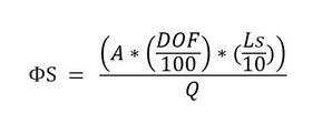
Where:
ΦS the residence time in seconds
A open cross-sectional area in cm3
DOF degree of fill percent
LS length of the section in millimeters
Q volumetric flow rate in cubic centimeter per second
Assumption = Conveying sections are starved
The 2 RT’s are then added together to estimate the total residence time in the extruder. For instance, let’s assume a ZSE 60 MAXX @ 40/1 L/D with 1.66/1 OD/ID ration processing a PP formulation @ 800 kgs/hr, 680 screws rpm, and with this screw design:

The total length of the above screw for the ZSE 60 MAXX is 2,460 mm with 1,920 mm flighted elements and 540 mm of non-flighted/mixing elements. The following applies to the ZSE 60 MAXX:
| ZSE 60 MAXX | |
|---|---|
| Free volume | 152.9 |
| H (flight depth) | 12.2 |
| D (screw diameter) | 61.6 |
| A (cross sectional area) | 23.15 |
And the RT is estimated as follows:
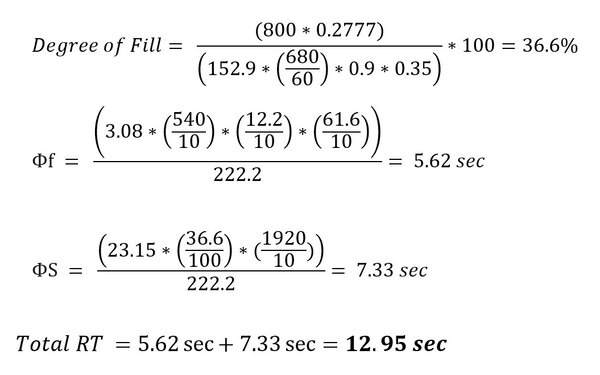
Editor’s note: RT refers to the average residence time and is different from the Residence Time Distribution (RTD), which will be a subject of a separate discussion in the next Leistritz Extrusion Twin Screw Report.
Technical tipInstall insulation blankets on barrels, dies and adapters
Insulation vests can be wrapped around barrels, adapters and dies. With a removable insulation blanket, you can remove the insulation whenever necessary, then easily reinstall it yourself! In addition, removable insulation allows you to easily conduct periodic inspections and maintenance of equipment to identify and remedy equipment problems and inefficiencies.
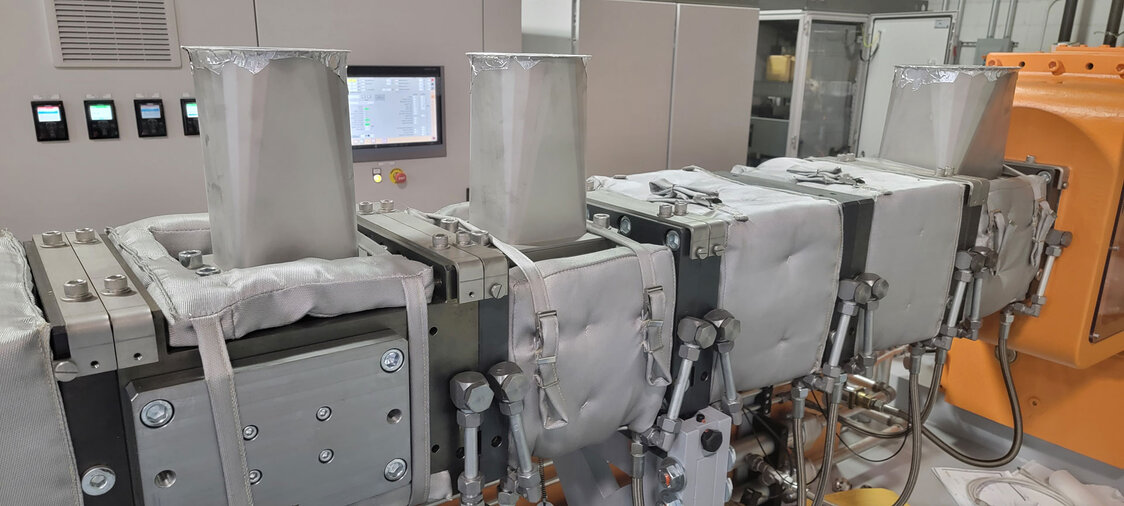
ZSE MAXX barrels with insulation blankets
Some advantages over bare steel components include:
- Improved operator safety by reducing burn hazards resulting from direct contact with high temperature parts
- Decreased energy costs (they often pay for themselves)
- More uniform component temperature setpoint by reducing PID temperature controller cycling
- Reduces the heat load on HVAC systems
- Extended life of componentry by reducing exposure to the environment and shielding parts from accidental damage
Tandem extrusion capabilities expanded in Leistritz NJ process development process laboratory
There is a trend to combine multiple extruders sequentially in one system to extrude unique products. Tandem extrusion systems allow effective L/D ratios of 100+ by stringing together a series of unit operations using different type extruders at different screw diameters and screw rpms to take advantage of the unique performance of each type.
The Leistritz process development laboratory includes:
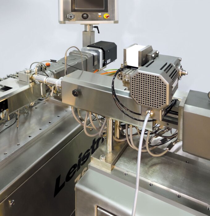
Tandem extrusion: Counter-rotating TSE mated to co-rotating TSE
- 5 twin screw extruders: ZSE 12 to ZSE 50 MAXX
- Strand, underwater and hot face pelletizing (air quench and water quench)
- 40+ Feeders: pellets, powders, fibers, liquids, reclaim
- Downstream: film/sheet, tube/profile
- 50 mm to 1 meter in width film/sheet samples
- Up to 5-layer coex structures
- Lamination of substrates
- 3D filament extrusion
- Supercritical injection: foaming and stripping
- Devolatilization: multi-stage, atmospheric and vacuum venting
- Tandem TSE system setups - now available!
You are welcome to contact us to discuss your process development needs.
Technical tipMezzanine and feeder re-loading guidelines
Twin screw systems use customized support structures (or mezzanines) to integrate loss-in-weight feeders and material handling equipment with design criteria as follows:
- Per OSHA regulations, the minimum clear height under a mezzanine according is 7 ft, the deck height must be 8 ft or higher (depending on the steel deck joist) to allow for hanging lights, conduits and piping and fire sprinklers (7 ft applies to the height above the deck).
- To minimize time in refill mode, the LIW (or volumetric) feeder refill device should be capable of delivering the material at 8 to 10 times the maximum running rate of the feeder.
- The capacity of the surge bin/refill hopper (or vacuum loader) must take into account the maximum rate and hopper size of the LIW feeder
- For powders/granules/flakes feed streams, hopper angles are based on the angle of repose of the material and flow characteristics
- Agitators or other type of flow aids may be required
- The interior surface finish of any/all vessels should be at #4 RMS or better.
- The mezzanine design should accommodate whether any feeders need to be movable
- Feeders for low bulk density powders should be positioned to minimize the vertical drop distance that causes fluidization of the powder
- Pre-fabricated, light duty mezzanines should be avoided, as these catalog items are often “light duty” and not suited for the application
- Plant ergonomics must be considered, i.e. stairways should be integrated into the design
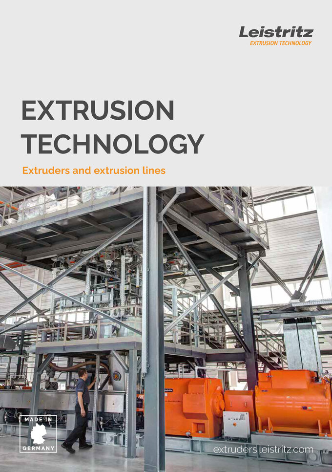
Leistritz Extrusion Technology overview brochure
A 16-page brochure describes the range of twin screw technologies and services available from Leistritz.
Leistritz Extrusion 2023 Calendar of Events
| Mar 28 - 30 | Plastics Technology PTXPO 2023 Conference, Chicago/IL |
| May 2 - 4 | Plastics Industry Association Re|Focus Summit, Minneapolis/MN |
| May 16 - 17 | Bioplastics Leistritz Twin Screw Extrusion Workshop, Branchburg/NJ |
| June 7 - 8 | Plastics Recycling LATAM, Mexico City, Mexico |
| July 24 - 28 | Controlled Release Society Annual Meeting, Las Vegas/NV |
| Sept 18 - 20 | SPE Color RETEC, Columbus/OH |
| Oct 22 - 25 | PharmSci 360, Orlando/FL |
| Nov 7 - 10 | PlastImagen, Mexico City, Mexico |
| Nov 15 - 16 | AMI Plastics Extrusion World Expo N.A., Cleveland/OH |
| Nov 28 - 30 | Leistritz Twin Screw Extrusion Workshop, Branchburg/NJ |
For additional information on anything contained in this newsletter call 908/685-2333 or e-mail sales@leistritz-extrusion.com
We look forward to serving you in the future
Team @ Leistritz Extrusion,
Leistritz Extrusion
175 Meister Ave. Somerville, NJ, 08876, USA
Phone: 908/685-2333
E-mail: sales@leistritz-extrusion.com
Website: www.leistritz-extrusion.com