
The following is included in this e-tech newsletter:
- Comparing Co-rotating Twin Screw Extruder Configurations for PLA and PHA Bioplastic Resins
- Featured article to download: How to remove, clean, restage, and reinstall your twin screw set
- Highlighted TSE formula: peak shear and shear stress
- Leistritz expands New Jersey Process Laboratory
- Leistritz to participate in SPE Shape Extrusion Topcon
- Help prevent heat sink with insulation plate between barrel segments
- New Leistritz Extrusion Brochure
Comparing Co-rotating Twin Screw Extruder Configurations for PLA and PHA Bioplastic Resins
There are many grades of polylactic (PLA) and polyhydroxyalkanoates (PHA) resins. PLA is supplied as a pellet and requires high torque for processing. PHA can be supplied as a powder with a low bulk density. Both materials benefit from additives/lubricants and require optimized feed zones for successful processing in a co-rotating twin screw extruder.
Twin screw extruders (TSEs) are a preferred manufacturing operation to compound bioplastics. TSEs utilize modular barrels and screws. Rotating screws strategically imparts shear and energy into the process. Since both PLA and PHA materials are heat and shear sensitive, modifying standard screw designs generally facilitates improved processing.
Test #1
PLA (NatureWorks™ 2002D) pellets were processed on a ZSE-27 HP model twin screw extruder (27 mm dia. screws, 4.5 mm flight depth and 1.5 OD/ID) and a ZSE-27 MAXX twin screw extruder (28.3 mm dia. screws, 5.7 mm flight depth and 1.66 OD/ID). The TSE screws rpm was set at 300, 400, 600 and 1200 rpms. At each rpm the rate was increased until a boundary condition was encountered, which ranged from 60 kgs/hr at 300 rpm to 160 kgs/hr at 1200 rpm. All samples were torque limited. The ZSE-27 MAXX yielded approximately 10% higher rates with lower melt temperatures as compared to the ZSE-27 HP model. It seems that the gentler melting mechanism inherent with the MAXX design consumed less torque and allowed higher throughputs, while the lower average shear rate inherent with a deeper flighted TSE resulted in a lower specific energy and melt temperature. At elevated rpms the resultant melt temperature became problematic with both models.
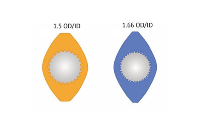
Comparison ZSE 27 HP (1.5 OD/ID) vs ZSE 27 MAXX (1.66 OD/ID)
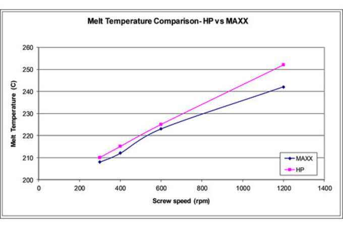
Melt temperature PLA at various screw rpms
Test #2
A melting experiment was performed processing PLA (NatureWorks™ grade 4032D) using three screw designs. PLA pellets with varying lubricant levels were processed on a ZSE 27 MAXX twin screw extruder (28.3 mm dia. screws, 5.7 mm flight depth, 1.66 OD/ID) at different screw rpms with a constant feed rate of 45 kg/hr. Various screw designs were compared with different melting sections. Delaying and modifying the melting zone resulted in lower torque and melt temperatures. Formulations were also tested with and without lubricants, and both surface type and immersion melt probe. As expected, when the lubricant content was increased, the torque and melt temperature both decreased. In all cases the immersion probe read a higher melt temperature.
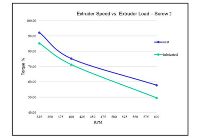
Torque vs screw speed PLA with and without lubricant
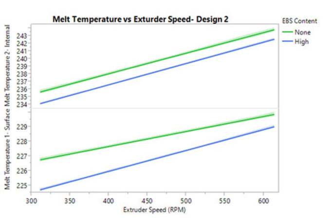
Melt temperature vs. screw speed PLA with and without lubricant and surface vs. immersion probe
Test #3
A series of experiments were performed processing an experimental grade PHA resin with 10% impact modifier and various additives on a ZSE 27 MAXX twin screw extruder. Initial testing was performed with a standard PE type screw/barrel design and the attainable rate was limited to 12 kgs/hr at 300 screw rpms. At higher rates and screw rpms the feedstock material backed-up in the feed throat and premature melting occurred. A 2nd design that lengthened the melting zone and added atmospheric vent early in the process section facilitated an increase in attainable rate to 62 kgs/hr at 800 screw rpms.

Comparison screws/barrels #1 and screw/barrels #2 used in test
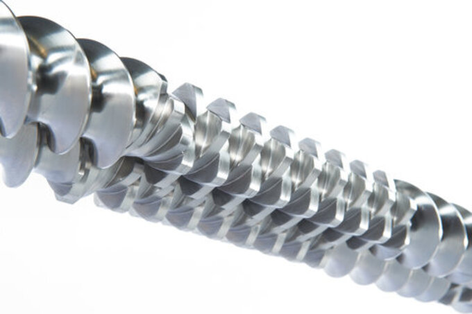
Co-rotating screw elements on shaft
Article to download
Reprinted courtesy of Plastics Technology Magazine
As compounders move from one job to the next, time is money. Twin screw compounding extruders are designed with removable elements assembled on splined shafts and designed to optimize the process. And when the run ends and it's time to move to the next one, these screw sets need to be removed and swapped out for a new set. It is also important to periodically disassemble and reassemble screws as part of a preventative maintenance program. How quickly and efficiently screw changes are carried out has direct impact on the bottom line. This article details best practices that should considered to expedite this process.
What you will learn:
1. CLEANING AND INSPECTION. How to do an initial cleaning and check for nicks and gouges.
2. REBUILDING THE ASSEMBLY. Proper positioning of the components and application of anti-seize compound.
3. REINSTALLING THE SCREWS. Ensure that the gearbox output shafts and couplings are in the correct position.
4. TOOLS/PARTS. Make sure your workshop is well equipped with a variety of tools and any spare parts you might need.
To download the complete article CLICK HERE.
TSE formula: Calculating peak shear and shear stress in a TSE
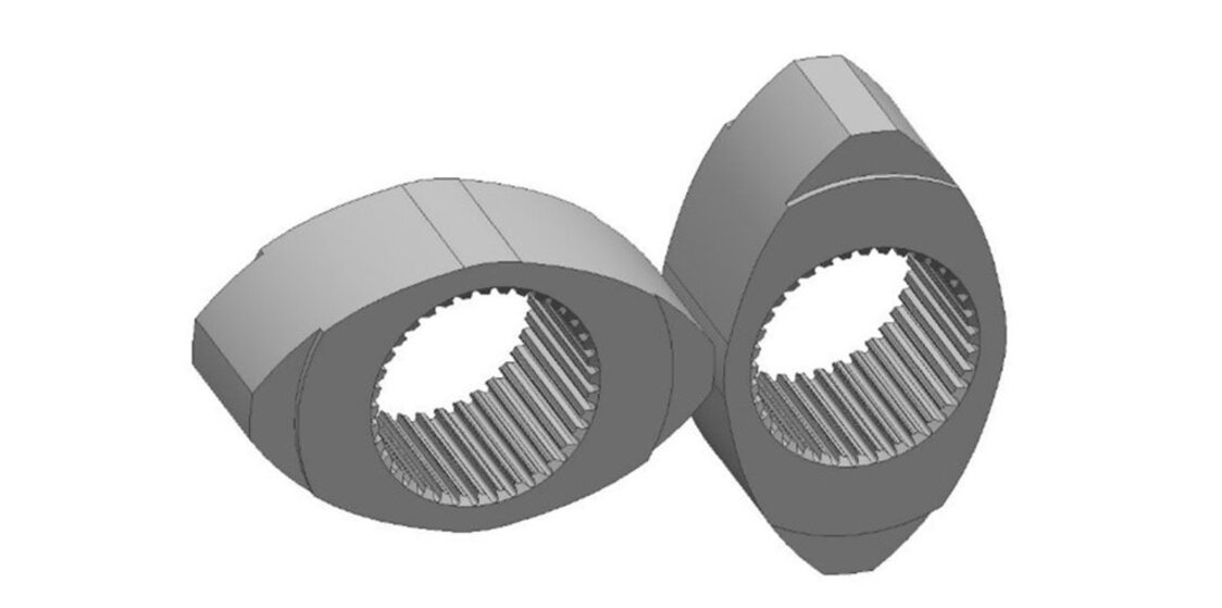
Example kneaders used for mixing
The peak shear in a co-rotating twin screw extruder facilitates dispersive mixing, and can also cause degradation or de-structuring of components (i.e. fibers) in the formulation, and is calculated as follows:
Peak shear rate = (π*D*n)/(h*60)
D = screw diameter, n = screw rpm, h = overflight gap (gap between kneader and barrel wall)
So, for a TSE with a 60-mm OD screw and 0.3-mm overflight gap, the peak shear would be calculated as follows: ZSE − 27 = (π * 60 * 600) (0.3 *60) = 6280 s−1
The formula can be used as a rough estimate to match rpms for TSEs with different diameters, or to estimate the shear at a particular screw rpms. Peak shear rate can be used to calculate shear stress, which is the critical factor to accomplish dispersive mixing:
Shear stress = peak shear rate × viscosity
Increased cooling can increase the viscosity of the melt to help achieve dispersive mixing. It should be noted that shear stress is not a measurement of extensional mixing, which is much more complicated to calculate and generally uses computer modeling, but it does provide an easy to calculate benchmark for insight into the dispersive mixing effect.
Leistritz to participate in SPE Shape Extrusion Topcon
Mix and meet with experts from the extrusion industry!
SPE Shape Extrusion Topcon
May 12-14, 2020, Nashville, TN
The SPE Shape Extrusion Topcon is a 3-day program sponsored by the Society of Plastics Engineers Extrusion Division that starts with a ½ day fundamentals session and followed by 2-days of advanced presentations relating to the latest extrusion technologies to extrude precision parts and products. Leistritz Extrusion will contribute to the program as part of the technical program and also as a corporate sponsor. For more details see HERE.
Test, don’t guess!
Leistritz installs a crammer assist feed mechanism for low bulk density feedstocks
The Leistritz USA process laboratory includes 5 twin screw extruders with L/D ratios to 60/1 and can test a 50 gram batch or run a process @ 1000 kgs/hr. Capabilities include:
- Pelletization: strand, underwater and air quench types
- Film and sheet: lamination, coex structures
- Tube and profile: medical devices, coex and foamed products
- Foaming: CBSs and supercritical injection
- Devolatilization: atmospheric, vacuum venting and stripping agents
- Reactive extrusion
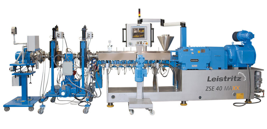
ZSE 40 MAXX with screen changer, gear pump, melt diverter/screen changer and underwater pelletizer
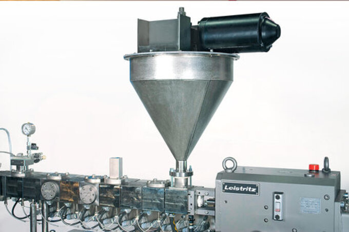
Crammer assist device recently installed into the Leistritz NJ process laboratory
A recent addition includes a crammer assist mechanism to help run low bulk density flakes and fibers. A typical feed system for fluffy materials is configured as follows:
Custom refill bin integrated with weigh belt with rotary valve discharge
Weigh belt feeder complete with AC motor/drive
Crammer assist device: The crammer assist device uses a screw auger that mates with the ZSE-MAXX feed throat to densify and push low bulk density materials into the feed throat and includes:
- Single screw auger with agitator assist arms, hardened steel
- Conical hopper with internal stator bars, stainless steel construction
- Custom latched lid with provision for multiple feed streams
- Mounted directly to ZSE-MAXX feed throat
- AC motor/drive
The Leistritz process laboratory provides access to 40+ feeders for pellets, powders, fiber, heated/ambient liquids and supercritical fluids. Contact us today to see how we can help develop your process in in the lab!
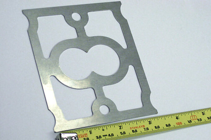
Example of ss heat barrier insulation gasket
The easiest way to solve this problem is to install a heat sink insulation plate between the flanges of the feed barrel and barrel #2. These gaskets are typically 1mm thick, and it's recommended to stack two together for better insulating performance. There will still be some heat conduction through the bolts, and of course the screw shafts, but not nearly as much as without the insulation.
Many operators don't realize the importance of an insulation plate and discard it when disassembling the barrels. Don't do that! Keep your feed barrel temperature cool and under control.
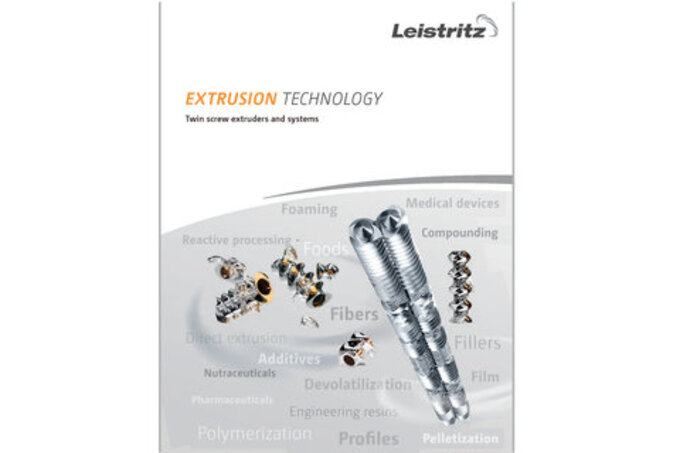
Leistritz Extrusion Technology brochure
A 16 page brochure describes the current range of twin screw technologies and services available from Leistritz. To download the Leistritz Extrusion Technology brochure CLICK HERE.
For additional information on anything contained in this newsletter call 908/685-2333 or e-mail
sales@leistritz-extrusion.com
Your Leistritz team,
Leistritz Extrusion
175 Meister Ave. Somerville, NJ, 08876, USA
ph: 908/685-2333
email: sales@leistritz-extrusion.com